Okay, so I am going a little out-of-order from how I am building the table. The fence is mostly done, but I am still working on tweaks. I only want to do one post on the fence so i will publish that post once I am happy with how the fence is performing.
In the meantime, I can write about the cabinet. It’s not done yet. 🙂 However it is to a point that it is useable. What I have left is the drawers, the door, the back, and dust collection. Those will be discussed in a future post.
 The cabinet is largely made from birch plywood from a big box store. I drew a rough sketchup drawing so I could get an idea of how much plywood I would need. Turned out I needed a sheet and a half. I went ahead and bought two full sheets. Always good to have extra on hand. I went with ~3/4″ thick ply for its strength.
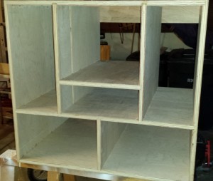
The primary joinery is dado and rabbets. Normally I would leave it at that and just clamp it up. however, it is a shop project so I also used screws and nails. With the size of the cabinet, it made it easier to square up and hold together while the glue dried.
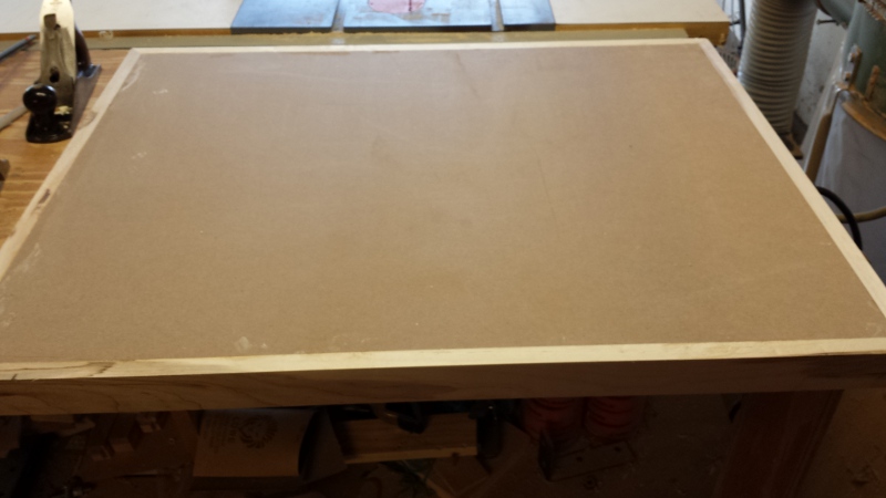
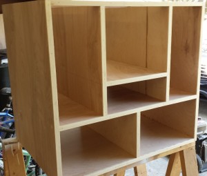 I decided against a face frame. I wanted to maximize the storage potential of the cabinet. After the glue dried I edge banded all the front facing plywood edges with a hardwood. This is largely so I don’t have to look at the plywood edges every day. 🙂 I fitted each piece individually, and just simply glue and nailed each one in place. (Hey it is a shop project after all!)
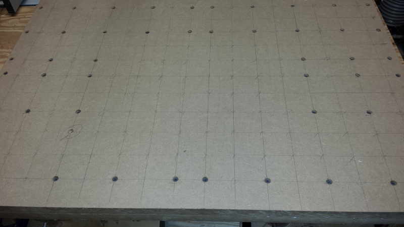
One of the goals I had with the cabinet is that, like my hand tool cabinet, I wanted it to be able to change it as my needs changed. I have actually designed that I can change the height of the table. That way if I ever have a need to match the height to a bench or other machine, I can do so with minimal modification. The space between the cabinet and the top can be changed out. It also has a lot of support to help keep the top flat. More of the flexibility will come as I build the drawers, and I will go into more detail once those are complete. The back won’t be glued in, just simply screwed in. This will help make modifications in the future easier.
The power setup for this was fairly straight forward. I bought a power switch at a woodworking show. I wanted a power cord that came out the back, and the cord that came with the switch wasn’t long enough. After some playing around with the switch, I decided not to modify it in any way. Instead I bought a replacement tool power cord, a junction box, and an electrical outlet. I wired up the cord to the outlet, and put the junction box attached to the interior of the cabinet. After using a tester to verify it is wired up correctly, I just simply plugged the switch into the outlet, and the plugged the router into the switch.
One of the things I hated about my previous router table was it wasn’t easy to move. With a small shop, having the ability to move machines around is vital. So the bottom of the cabinet is held up by casters.
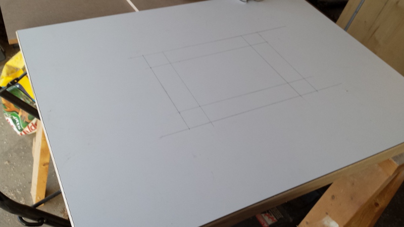
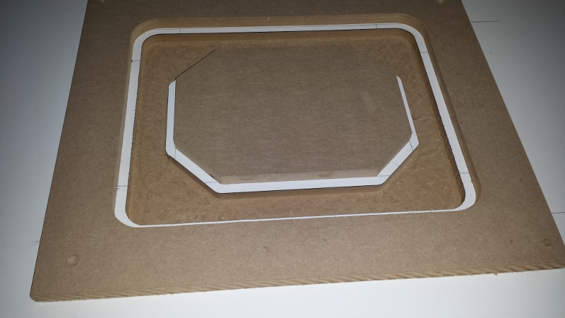
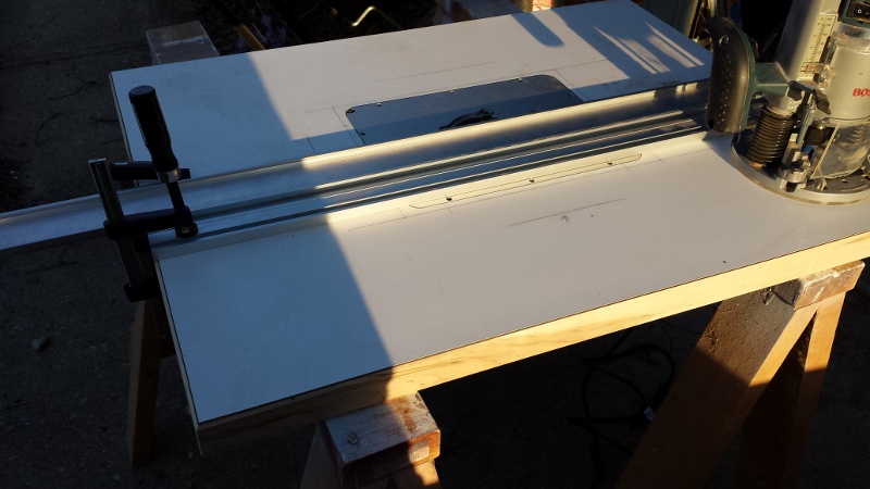
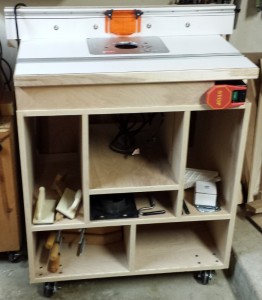 Finally, the top simply sits on top of the table. There are blocks that hold the table in place laterally, but it just simply uses gravity to hold it in place. I made sure that there was no lateral movement (side to side and front to back) at all.
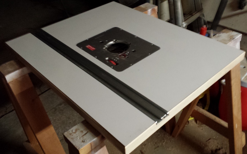
Despite the unfinished state of the cabinet, it is complete enough that it is now a functioning router table! I will write a full review of the lift, but I can say my initial impressions of it are great!